Micro Electric RC plane
This page is about an R/C airplane designed using the eMachineShop CAD software. The CAD drawing is available in the FREE eMachineShop CAD package which you can download. The CAD drawing is actual size so you can determine the size of everything from the wing to the neo magnets.
The Micro Electric R/C plane project goals where: • Simple construction • V-Tail • Adjustable CG • Attractive design • Durable • Two channel • Actuators flush mounted • Modular for easy repairs.

Fig. a – Completed Project
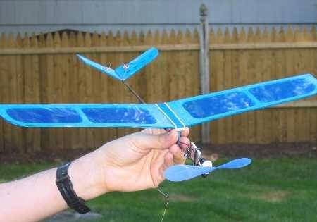
Fig. b – Overview
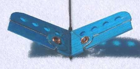
Fig. c – Actuators
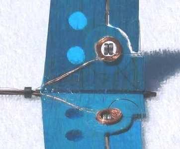
Fig. d – Actuators (cont.)
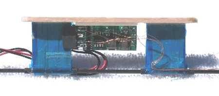
Fig. e – The PCB
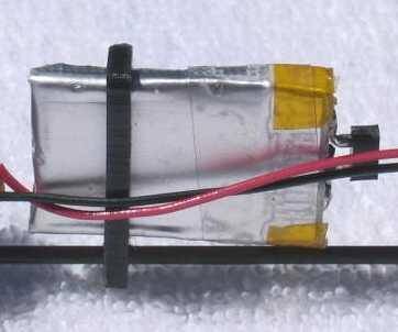
Fig. f – The Battery
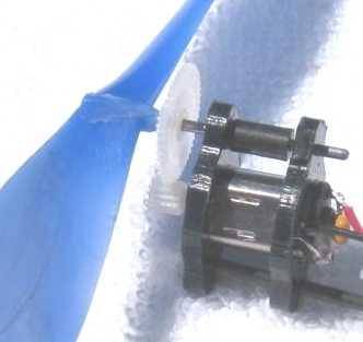
Fig. g – The Motor
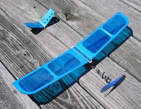
Fig. h – In the sun
A CAD drawing is available here in the FREE eMachineShop CAD package which you can download here. eMachineShop is the first true internet machine shop – where you can get custom parts via the internet. But a good garage is all you need to make this plane.
The CAD drawing is actual size so you can determine the size of everything from the wing to the neo magnets.
You can spray-glue the CAD printout to guide cutting.
|
The image to the right shows an overview of the features (from rear to front):
At first I used a 145mah lipo and got best flight times around 7 min. Later I switched to pair of 3.5″x9″ foam wing cores from slowfly.com and 250mah lipo and now getting 15 min. |
|
The main wing is flat like a classic toy balsa glider, making construction quick and easy. The RTF weight is just over an ounce (1.08 oz). I named the plane the “Ouncey”. CG is a bit forward of the middle of the wing.
The covering is 0.6 oz/sq yd. Cover the bottom surface first. Then brush on some flour and brush off the excess. This prevents the covering from sticking to itself, after construction, when you grab the wing the wrong way (a lesson I learned the hard way – twice). I found that a bit of glue stick on the balsa holds the covering in place while working with it.
Several crashes, some straight down, have proven the durability of this light design. It’s not quite as light as the pure stick designs but it’s a lot more practical and durable.
Make sure you have some washout on the main wing by twisting a bit while applying a heat gun to the covering. The trailing edge at the tips should be 1/16″ to 1/8″ higher than the leading edge. Without this you will have unstable flight with strange dives etc.
|
The small black thing at the carbon fiber rod is a C clip made of plastic to retain the actuator wires but tape will do fine. CA fiberglass material around the coil hole to prevent the balsa from cracking:
|
The actuators are mounted near the fuse to keep weight low for stability. Actuators are usually mounted perpendicular to the control surface – it’s a little easier but it obstructs air flow a bit. The flush mount approach is much nicer in my view.
The center of the coil must be in line with the hinge.
For the coils I used .005″ magnet wire but if I were to do it again I would go down to about .003 as I had to put a 18 ohm resistor in series to avoid over deflection! My coil came out at 7 ohms and had plenty of power at 0.5V 60ma! The JMP requires at least 10 ohms.
The hinge uses a piece of a rubber band straight down the crack with clear tape alternating between the fixed and movable surfaces. I cut 1/2″ tape to 1/4″ and used 4 strips per side (2 on fixed surface, 2 on movable surface).
The V-tail assembly was CA’ed to a length of wire insulation to make adjustment and disassembly easy. Cut the insulation a bit longer than the tail to be sure no CA gets inside the insulation, which would prevent removal of the tail for repair.
See the CAD drawing for dimensions.
|
This close-up of the actuators reveals some detail. I used .015″ music wire to connect the neo magnets to the control surface. The bend is a bit tricky:
If you have a lathe you can take the following approach for the winding jig:
|
To bind the coil during winding:
Next time I plan to try using just CA a few times during winding and using plastic bag film in jig to avoid bonding to jig. |
|
The PCB (receiver / actuator driver / motor driver / BEC) is a JMP (great product). I hot glued a small rectangle of plastic to the side of the edge connector without wires. This and the wires help retain the board in position. A thin strip of foam tape on the bottom of the main wing support helps retain the receiver. Placing the receiver in between the wing mounts instead of on the side is a bit more aerodynamic and better protected. The JMP board is supposed to be ~2″ from the battery and motor so consider making the rear wing support narrower than the forward support. Attach the wing support to the wire insulation (over the CF rod) with a rectangle of fiberglass fabric .75″ x .75″ (prior to covering). The balsa at the top is setup for a single rubber band to retain the wing. Previously I tried using 4 small neo’s. I’m undecided which way is best. The neo’s add a little weight and complexity and the wing falls off almost every landing but its super fast to mount the wing. The rubber band is lighter but also comes off often and gets lost. |
|
The battery mount is just a piece of thick plastic with a hole and a slot. See the CAD drawing for dimensions. |
|
|
The motor and li-po came from a Wattage Flyer (~$35). At first I used the gears and prop that came with the WF but in the version shown I changed to a more efficient and larger prop (with slower gearing). The motor mounts were made of thick plastic sheet with three holes. See the CAD drawing for dimensions. The motor and prop are angled down 4 deg. Everything is press fit with no CA. This allows adjustment of prop perpendicularity to fuse (but you might prefer to lock everything with CA or epoxy). The shaft is music wire. The black plastic cylinder keeps the shaft from sliding. The large gear is pushed up to the prop and CA’ed so it will not move in a crash – only the black retainer cylinder will slide. Check mesh at several angles of rotation – must have a little play and not bind at all. The ground wire is soldered to the motor lead AND to the case for noise reduction. A capacitor across the leads also reduces electrical noise. For wire I used part of a multi-color ribbon cable. |
|
Taking some sun on the deck, ready for flying. Some of the suppliers used: Sponsored by the Grasshopper winch.
|
|