This tutorial will step you thru creating a 3D (three dimensional) part – a flywheel. 3D parts are made from blocks of material and can have recesses, rounded edges, slopes, etc.
 |
If you view the above video, you can skip the text below which summarizes the video.
It is assumed that you reviewed the 2D tutorial. Start the eMachineShop CAD application: double click on the desktop icon. Create a new design: choose File | New | Blank Design. Check that the ruler indicates INCHES. If not, on the toolbar click the button marked MM and verify that the ruler now shows INCHES. |
 |
Choose Job | Material and select 6061 (a popular aluminum). Click OK. |
 |
On the left toolbar click the Circle button. Move the mouse to the middle of the workspace
and click. Note that all clicks of the mouse and dragging refer to the Left mouse button. Now move the mouse away from the center and click
again. Don’t worry about the exact size of the circle. Next set
the exact size numerically. Let’s suppose we want a three inch flywheel.
Go to the numeric bar above the workspace. Enter 3 in the diameter field and press the Enter key on the keyboard. Notice that the size
of the circle has changed. Now let’s adjust the zoom level to make the circle fit the screen by pressing the equal key on the keyboard. |
| |
We need to specify not just the diameter of the flywheel circle but
the thickness of the flywheel disk – the third dimension. This third
dimension is referred to as the Z axis – how far out from
the screen towards yourself the material should extend. In the Z control of the numeric bar enter 0.5 and press Enter on keyboard. |
 |
Let’s take a look at our part
in 3D to see what we have done so far. Click the Pyramid button. Drag
your mouse on the 3D view to rotate the view. On the right side of the
3D view dialog look for the scroll bar. Drag the scroll bar to adjust
the size of the 3D view. Close the dialog by clicking on the X button
in the upper right corner. |
 |
Next let’s create a hole in the center of the flywheel. To do this we’ll draw a smaller circle. To insure that the small circle is exactly at the center of the large circle we will use the SNAP feature. On the LEFT TOOLBAR check that the SNAP TO LINES button is pressed in – this button has a picture of an arc and a straight line on it. This button is located near the bottom of the left toolbar. If it is not pushed in, click on it. |
 |
Click the circle button again.
Move the mouse to the center of the large circle. When you are at the
center you will see a small square to indicate that the SNAP feature
found the exact center. If you don’t see the small square, move the
mouse around the center area until you get the small square. Got it?
OK, now click to start the new circle. Drag the mouse an inch or so
and click again. Now we will set the exact size of the center hole.
Go to the numeric bar above the workspace. Click in the rightmost control
which represents the circle diameter. Erase the current value, enter
0.5, and press the ENTER key on the keyboard. Notice that the size of
the circle has changed. Now we need to indicate that this circle is a hole. On the numeric bar, in the Z value select Air Inside. |
 |
Choose View 3D. You should
see a thick disk with a hole. Close the 3D view by clicking on the X
button in the upper right corner. |
|
Now, let’s create the recessed
feature which makes the inner portion of the flywheel thinner. We need
two more circles to accomplish this. We could draw the circles as before
but we’ll use CUT and PASTE instead – a trick that saves time. Click
on the large circle. Notice that it changes color to indicate it is
selected. On the menu choose EDIT COPY. Then choose EDIT PASTE. We have
just made a copy of the outer circle – you can’t see the copy because
it’s directly on top of the first circle. Now go to the numeric bar.
Click in the rightmost edit control which represents the circle diameter.
Replace the current value with 2.5, and press the Enter key on the keyboard.
Notice that the size of the circle has changed. Now let’s indicate this
line is a recess. On the numeric bar in the Z edit enter minus 0.2. This indicates
that the material is to be recessed by two tenths of an inch. Let’s
review how this works in a bit more detail. A Z value specifies
the height of the material RELATIVE to the height of the material at
the next outer line. A negative value makes the material LOWER than
the next outer material – a recess. A positive value makes the material
HIGHER – a protrusion. Now click the OK button to close the dialog.
Let’s take a quick look at the 3D view again. On the MENU choose View | 3D. You should see a thick disk with a recess and hole. Close the 3D view. Now let’s make the center hub. Click on the largest circle. On the
menu choose EDIT COPY. Then choose EDIT PASTE. Now go to the numeric
bar. Click in the rightmost edit control. Erase the current value. Enter
1, and press the Enter key on the keyboard. To indicate that it’s a protrusion on the numeric bar in the Z edit enter 0.2. |
 |
Now we will copy the recess
to the Bottom view. Locate the second to largest circle. Click on this
circle. Now hold down the SHIFT key on the keyboard. While holding the
SHIFT key click on the next smaller circle. Now release the SHIFT key.
The two recess circles should be highlighted in a different color. On
the MENU choose EDIT COPY. Next switch to the Bottom view by going to
the menu and choosing VIEW BOTTOM. We are now viewing the drawing of
the bottom side of the flywheel. Now choose Edit Paste. We have made
a copy of the recess on the bottom view. Let’s take a quick look at the 3D view again. On the MENU choose View 3D. Spin the flywheel to both sides to verify that the recess is now symmetrical. Close the 3D view.
|
 |
Switch back to the top view
by choosing on the menu VIEW TOP.
Finally, let’s make six holes around
the recessed area to complete our flywheel. First we will place one
hole equally spaced between the outer and inner recess circles. To do
this we will draw a temporary guide line which we will subsequently
delete. Using temporary guide lines is an important technique. On the
left toolbar click the straight line button. Now move the mouse to the
top of the second largest circle – that is the top of the larger recess
circle. When you are at the top of the circle you will see a small square
to indicate that the SNAP feature found the exact top. Haven’t found
it yet? Move the mouse around until you get the small square. OK, now
click to start the straight line. Now move the mouse to the top of the
next smaller circle. That is the top of the second smallest circle.
When you see the snap square click to end the straight line. Again,
the straight line is just a guide to help us locate the next small circle. |
 |
Now let’s remove the straight
guideline. Click on the straight line to select it. On the keyboard
press the DELETE key. The line is now erased. The purpose of the line
was only to place the new hole exactly at an equal distance between
the rim and the hub. Let’s take a quick look at the 3D view again. On the MENU choose View 3D. Notice the hole in the recessed area. Now we just need 5 more holes and we will be finished. Close the 3D view. |
 |
We will now use COPY, PASTE,
and ROTATE to make the final 5 holes. First, on the numeric bar, in the Rotation Step Angle box enter 60 to prepare for the proper spacing of the holes at 60 degrees
each, because 360 divided by 6 is 60. Now click on the small circle we created a minute ago. On the menu choose EDIT COPY. Then choose EDIT PASTE. We now have our second hole but it is directly on top of the first. We need to rotate the second hole away from the first hole. On the menu choose LINE, ROTATION BY DRAGGING. You will see rotation indicators near the circle. At the center of the circle you will see a very small circle. Drag this very small circle to the snap center of the flywheel – that is the center of the entire flywheel. The snap feature will guide you again with a small square. We have now set the center of rotation. Now press the "R" key on the keyboard to NUDGE the circle to the next rotation position according to the 60 degrees we specified. It’s OK that the circle moves to the left when you press the "R" key. We are almost finished. Choose EDIT COPY and EDIT PASTE again. And again press the "R" key. Three more to go. EDIT COPY and then EDIT PASTE and then "R". Two more to go. EDIT COPY and then EDIT PASTE and then "R". One more time. |
 |
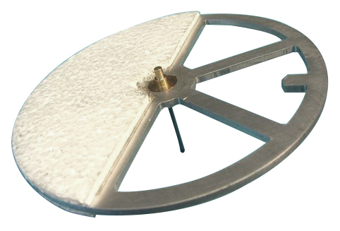
Now let’s take a final look
at the flywheel in the 3D view. On the MENU choose View | 3D.
You will see the final view of the flywheel. Notice the six lightening
holes. Our flywheel is complete!
For more advanced techniques on designing 3D parts see the Video Guides. Also see 3D design tips here. |