Custom Manufacturing Made Easy
eMachineShop offers CNC machining, sheet metal fabrication, 3D printing, injection molding and various finishing options. Simply upload your design, enter your specifications and get a reliable manufacturing quote.
- Over 50+ Metal and Plastic Materials Available
- Rapid Prototyping and Full Production Runs
- Quick Turn Times and Quality Assured Manufacturing
As Seen In:
Manufacturing Services
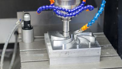
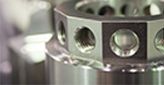
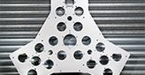
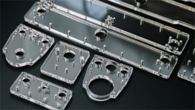
CNC Machining
Precision milling and turning for metal and plastic parts. Prototypes and production.
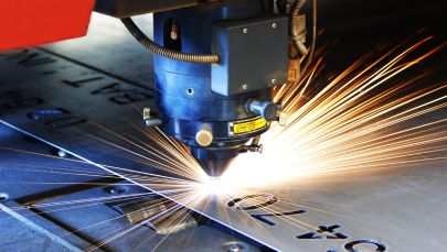
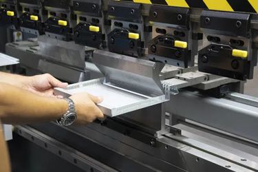
Sheet Metal Fabrication
Waterjet cutting, laser cutting, tapping, bending and finishes.
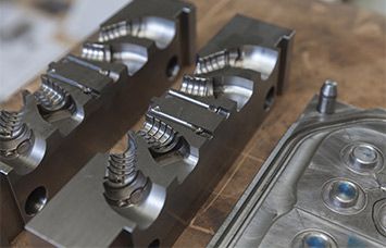
Injection Molding
Injection molding of moderate to larger quantities of plastic parts.
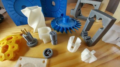
3D Printing
Rapid production of plastic and metal parts. Choose from a variety of colors.
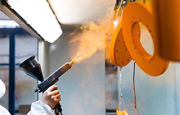
Surface Finishing
Powder coating, anodizing, electroplating, brushing, polishing.
Secondary Processes
A wide variety of secondary machining such as tapping, bending, countersinking.
Simplified Custom CNC Manufacturing
Upload your CAD files with any supplemental files for tolerances, threading, etc.
Select your material from over 50 metals and plastics, quantity, finishing option, and any special comments.
Get a fast quote using your own CAD files or an instant quote using eMachineShop free CAD software.
Easily place your order using our free CAD software or following a payment link included within your quote.
Why choose eMachineShop?
Prototype to Production – Order any quantity. No minimum or maximum limits.
Novices and Engineers – If you are new to custom manufacturing, try our easy free CAD software. If you’re a pro, just provide us with your CAD file.
Great customer service – We will be at your side from design to order tracking.
Free shipping – No charge for ground shipping in the continental USA.
Quality Ensured with Expertise
As a company committed to delivering high-quality products, we implement strict standards throughout our manufacturing processes to ensure accuracy, precision, and consistency. Our manufacturing facilities are equipped with top of the line equipment to accommodate rapid prototyping and production runs while maintaining tight tolerances and quick turn times. Our procedures ensure every manufactured part meets our high-quality standards and your specified requirements.
Experienced Technical Support
Technical Support Representatives are committed to providing quick and informative support
Dedicated Account Representatives
Support Resources and Tutorials
Proactive Recommendations
Comprehensive Quality Control
We implement quality control protocols to ensure your custom parts meet your specifications
Quality Assurance
Procedural Inspection Policies
Dimensional Testing & Defect Analysis
eMachineShop’s Quality Parts Guarantee
We ensure parts meet your standards and offer comprehensive customer support
Responsive Customer Support Agents
Corrective Action Recovery Plans
Continual Customer Feedback Integration
Upload your file
for a fast quote
Get a Quote
No CAD file?
Draw it easily with our CAD
GET FREE CAD
Our Software Solutions
eMachineShop offers a range of solutions and software tools that are specifically tailored to the needs of CAD designers and engineers to help streamline the design process and improve efficiency. With these resources, our goal is to make CAD design easy, efficient, and accessible for everyone.
What Our Customers Say