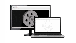
Gear Design Software
Design and customize a spur gear in minutes using eMachineShop’s gear design wizard.
- 100k+ CAD Users.
- 25+ Part Templates and Shapes.
Make a Custom Gear
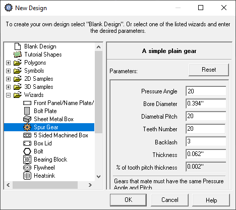
- Open eMachineShop CAD and select File > New.
- Expand the Wizards drop-down.
- From the list, select Spur Gear.
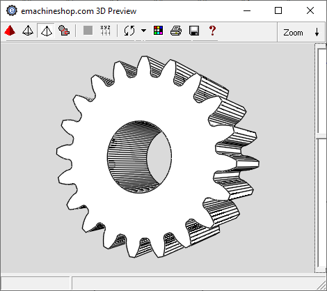
- Enter the desired parameters and click OK.
- In the workspace, add desired custom features as needed.
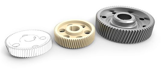
Steel is a popular choice when creating metal gears due to its high strength and low cost. Brass is also commonly used. Plastic gears are commonly used when cost or weight is a concern, or in cases of where gears may be exposed to dirt or not lubricated for long periods. Plastic gears can also be used as sacrificial gears to avoid damaging other components in case of a malfunction.
What is a spur gear and what is it used for?
A spur gear is among the most popular and common gear types, which is used to control the power, speed, and torque of mechanical systems. Spur gears feature a simple design and are economical and durable, making them reliable for most mechanical applications. The three primary types of spur gears are external tooth gears, internal tooth gears, and rack and pinion.
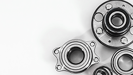
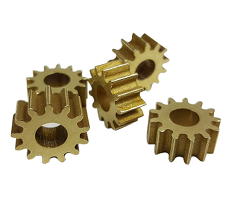
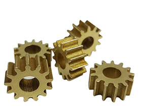
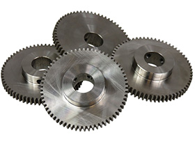
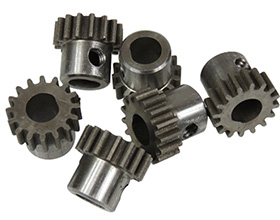
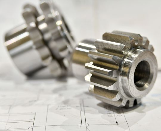
eMachineShop Gears Produced
What is important when designing a spur gear?
When determining a spur design, various elements need to be considered. These include the overall gear design and shape, size, material, pitch diameter, number of teeths, as well as the amount of profile shift. Other factors to take into consideration include whether there is heat treating, the type of tooth surface finish, the amount of backlash, the shaft mounting method, class of precision, the lubrication method, and the production process.
What is the module of a spur gear?
The module (m) of a spur gear is defined by dividing the number of teeth by the reference diameter. The diameter formula is determined by calculating the pitch diameter. This is achieved by dividing the number of teeth on a gear by the diametral pitch of the gear. Gears are only capable of meshing with each other when they contain teeth of the same module.
Gear drawing – How to draw gears?
Custom gear drawings can be created using gear design software, such as eMachineShop CAD, which enables users to add custom features and design elements according to their specific needs.
eMachineShop’s free CAD software was developed to enable both beginners and experienced CAD users to customize their 3d drawings online for free. Using the design wizard, a 3D gear can be designed and customized in minutes. The gear software features a free online gear generator and is easy enough to use for beginners. It includes a user-friendly interface, drawing tools, and built-in pricing and ordering functions.
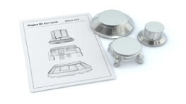
Making Gears with a DXF
eMachineShop’s free CAD software enables users to export their gear designs, to view them and edit if needed, and to instantly request a quote. Spur gears can be generated and exported as DXF from our browser and desktop CAD.
Model and manage your gear designs
Gear designs can be modeled using a gear maker, also known as a gear generator, a simple free online tool used for creating spur gears. A spur gear calculator uses parameters including the tooth count, gear module, and pressure angle to generate the key dimensions of an external spur gear. This helps you visualize a spur gear to ensure you have the right fit and to manage the gear size and undercut. Various gear design templates are available and can be edited to fit your needs, by entering the desired parameters. Beside the premade gear templates, there is also an option to draw custom gear designs, such as a custom involute gear, using eMachineShop CAD Design Software.
It is important to save gear designs in format that allows for dimensional accuracy when sharing or manufacturing the part. Popular file formats for gear designs are STEP, STL, IGES, DXF, and SVG.
Involute Spur Gears
Involute spur gears have teeth that are shaped like an arch, with the curved portion of the arch facing outward. The involute shape helps to reduce sliding friction between the teeth, allowing the gears to run more smoothly.
Gear drawing – How to draw gears?
Custom gear drawings can be created using gear design software, such as eMachineShop CAD, which enables users to add custom features and design elements according to their specific needs.
Making Gears with a DXF:
eMachineShop’s free CAD software enables users to export their gear designs to DXF files, to view them and edit if needed, and to instantly request a quote. Spur gears can be generated and exported as DXF from our free browser or Windows CAD.
Popular Materials for Gear Manufacturing
Gear material selection is important. Factors such as environment, function, and durability should be taken into consideration before having your gear machined.
Popular metals for gear production include steel, bronze, brass, and aluminum. Steel is used for its high strength and durability. Bronze provides added wear resistance and cosmetic appeal. Brass offers corrosion resistance. Aluminum is commonly used for its lightweight and strength.
Popular plastics used for gear production include nylon and acetal. Nylon is used since it is a tough and durable plastic that also offers corrosion resistance and low friction. Acetal offers strength and rigidity along with chemical resistant properties.
Gear Design Terminology

Pitch: The distance between adjacent teeth on a gear, usually measured in millimeters or inches.
Module: The ratio of the pitch to the number of teeth on the gear.
Pressure Angle: The angle between the tooth profile and a line tangent to the pitch circle.
Backlash: The amount of clearance between the meshed teeth on two gears.
Root Diameter: The diameter of the gear at the base of the teeth.
Tip Diameter: The diameter of the gear at the top of the teeth.
Face Width: The width of the gear between the two sides of the teeth.
Frequently Asked Questions
Q: What are the main gear design considerations?
A: Load capacity, center distance, shape of tooth, pitch, material and cost.
Q: What materials are best for high loads?
A: In most cases: steel, cast iron and bronze.
Q: What are the common gear tooth profiles?
A: The involute profile has good load-carrying capacity and smooth function. The cycloidal profile is often used for high speeds and accurate positioning.