Quick Start
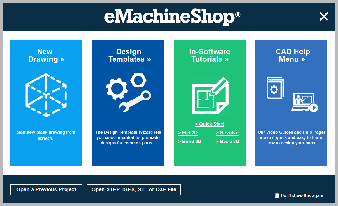
Getting Started
- Download and install eMachineShop CAD.
- Run the application.
- Select one of the tiles shown on the right to create a design, or to access learning resources.
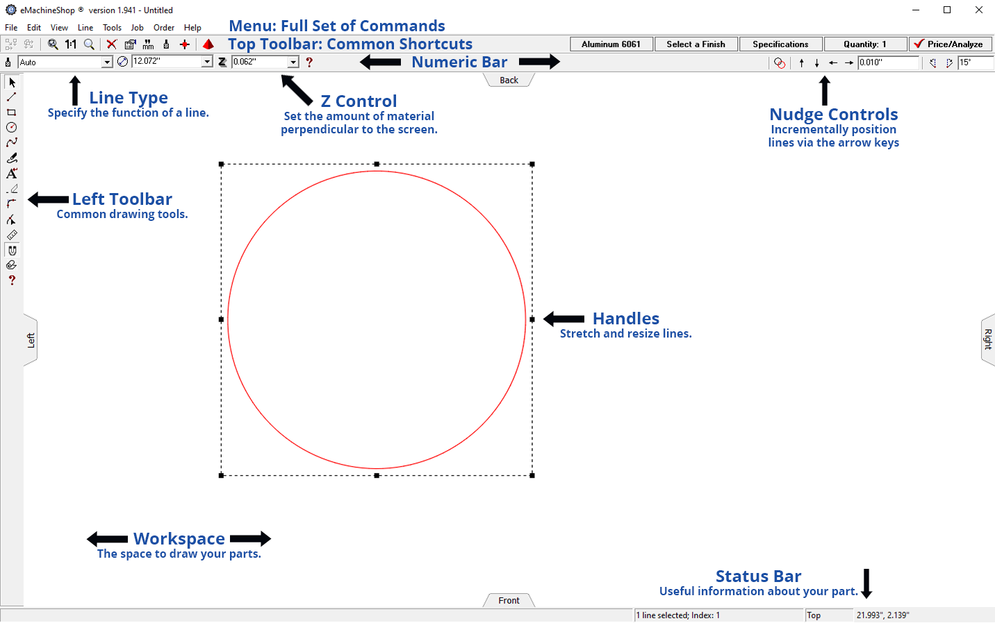
Screen Elements
The following labels will be used throughout the help guide:
Key Techniques
Draw Lines and Shapes
Use straight lines, circles and rectangles to shape parts and specify features.
- On the left toolbar, choose the straight line, circle, or rectangle tool.
- In the workspace, click the start and end locations.
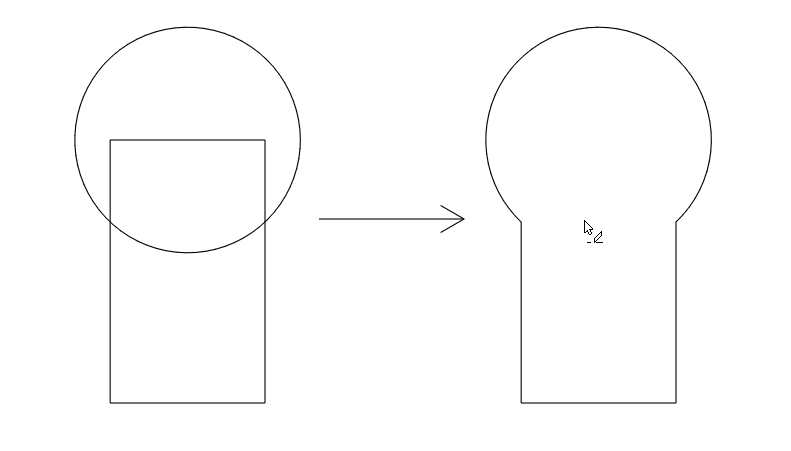
Draw Custom 2D Shapes
To create new custom shapes, use the Eraser tool to remove segments from intersecting lines.
- Draw overlapping straight lines, circles and rectangles.
- On the left toolbar, click the Eraser tool.
- Remove unwanted lines by clicking on them.
Accurately Size Lines and Shapes
- Select a line or shape.
- On the numeric bar, enter the desired size.
Accurately Position Lines and Shapes
- On the left toolbar, ensure the Snap to Lines button is pushed in.
- Drag a line or shape so one of the snap points on it meets a snap point (a small blue square appears) of another line or shape.
- In the top toolbar nudge controls, enter the distance you want to move the selection (e.g. 0.1).
- Use the nudge arrow buttons to position the item.
Numeric Bar Inputs
- Math formulas can be entered in place of numeric inputs.
Design a Part
Please first review Screen Elements and Key Techniques.
- If copying an existing part, measure the size and position of its features and make a dimensioned sketch.
- Choose File > New > Blank Design.
- Draw 2D shapes (see Key Techniques) corresponding to the shape and features of your part.
- For each line or shape, click it and in the Z-Control, set a value:
- Positive for a protrusion
- Negative for a recess
- “Air Inside” for a through hole
- To add features on different views, use the View menu and draw additional features on that view.
- To see your design, choose menu View > 3D.
- If your part requires bending sheet material, specify the bend location by drawing a straight line and choose Bend from the Line Type drop list.
- If your part requires threaded holes or protrusions, draw a circle and select Thread & Tap from the Line Type drop list.
- If required, set tolerances by choosing Job > Settings > Specifications
- Check your design for manufacturability and get an instant quote by choosing Job > Price/Analyze and resolving any errors.
- To order your part, choose Order > Review & Place Order