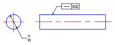
When looking at 2D drawings of 3D objects, certain drawing views may show a part feature as a straight line. Straightness tolerance specifies a tolerance zone within which the line element of a feature must lie. Since straightness is applied to an individual feature, this tolerance does not need to be related to a datum. The straightness symbol is sometimes used to ensure mating features (e.g. a dowel or other press-fit assembly) will create a tight fit without the use of fasteners.
The figure below shows two views of a simple cylindrical pin. In the side view, the cylindrical surface has a straightness tolerance applied to it. Because the surface is cylindrical, this tolerance applies to both the top and bottom line elements. The boxed symbols can be read “the top and bottom of the cylinder must lie between two parallel planes 0.02 apart”.

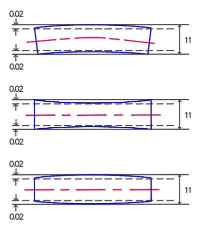
The additional figures below show three actual part conditions that would meet this tolerance.
