
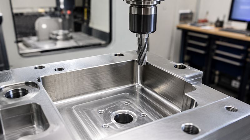
A CNC end mill is round. It cannot cut a perfectly square internal corner — physically impossible with a rotating cutting tool. Every internal corner on a machined part carries a radius equal to at least the tool’s radius.
Quick summary: Internal corners on CNC-machined parts always carry a fillet radius determined by cutter diameter. Designing to accept this — rather than specifying a “sharp” internal corner — avoids costly secondary operations like EDM or hand-finishing.
Why Does the Tool Geometry Force a Radius?
A ½” end mill can’t cut a 0” internal radius — the corner will always show the arc of the tool. Smaller tools produce smaller radii but cost more time and risk breakage on deep pockets.
What Happens If the Drawing Calls for a Sharp Internal Corner?
The shop either flags it back to you, or machines it with a smaller tool (slower, costlier) or a secondary EDM operation (costlier still) to achieve a true sharp corner.
What’s the Practical Fix?
Add a corner relief or design the mating part with a slight chamfer or radius that accommodates the machined fillet. This is standard design-for-manufacturability practice and avoids the cost entirely.
How Do You Specify This Correctly on a Drawing?
Call out a maximum allowable internal radius rather than “sharp corner.” Per ASME Y14.5-2018, an explicit radius callout removes ambiguity about what the shop should target.
FAQ
Is there a minimum achievable internal radius? It depends on pocket depth and available tooling — deeper pockets typically require larger-diameter, more rigid tools, which means a larger minimum radius.
Does this apply to external corners too? No — external corners can be machined genuinely sharp; it’s internal corners that inherit the tool radius.
Source: ASME Y14.5-2018. Related: GD&T Reference Guide