In GD&T, profile of a line tolerance is similar in many respects to profile tolerance. The major difference is that profile of a line establishes a two-dimensional tolerance zone that controls individual line elements of a feature or surface. Profile of a line is usually applied to parts with varying cross-sections, or to specific cross sections critical to a part’s function. Examples of parts where profile of a line could be applied include aircraft wings and housings used to seal out dust or water.
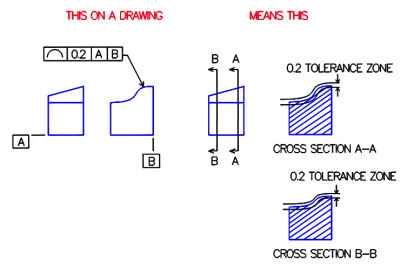
An example of profile of a line tolerance is shown below. In the left figure, profile of a line is applied to the top surface of a part. The boxed symbols can be read "each line element of this surface at any cross section must lie between two boundaries spaced 0.2 apart relative to datums A and B". The two right figures show sample cross-sections of the part with line elements that meet this tolerance requirement. Note that the tolerance remains the same for the line element even though the cross-section shape is different. Also note that two datums are needed to define the orientation of the cross section plane.
Because profile of a line can require multiple measurements at any number of cross sections, it is customary to specify the number of cross sections to be checked on the drawing.

