Online IGES Files Viewer
With eMachineShop’s free online IGES file viewer, you can simply upload an .iges or .igs file and the online viewer will open the design in a three-dimensional representation which you can rotate around multiple axes. eMachineShop’s online IGES file viewer also displays data from the design file such as basic measurements, file information, and more. eMachineshop’s online IGES file viewer renders and verifies file integrity of IGES files made with Solidworks, AutoCAD, Fusion 360, CATIA, Solid Edge, NX, Creo, FreeCAD, TurboCAD, Rhino, and more. Works for Mobile and Desktop and is Windows, Apple, Linux, Android, and iOS compatible.


Contact Information
Your quote will be emailed.
Advantages to using IGES files for 3D modeling
- IGES files can be read as text and edited by a wide range of CAD programs, making them ideal for open sharing models between different systems.
- IGES files are ASCII-based, meaning that the data is stored in plain text format, making them easy to read and understand.
- IGES files contain metadata such as color, material, and texture information.
- IGES files are compact, meaning they require less storage space than other file formats.
- IGES files are designed to be platform-independent, allowing them to be used on a variety of operating systems.
- The IGES specification is regularly updated to support the latest features of CAD programs.
Disadvantages to IGES files
While IGES files are popular among 3D model designers, there are a few potential drawbacks to this file format.
- IGES files can be very large: Since these files contain detailed text information of the geometry and topology, IGES (IGS) files can grow quite large making them difficult to share or store.
- IGES files may not store all the information correctly: Although IGES files are designed to preserve as much information as possible, they may not be able to retain all the data associated with a 3D model. This may result in loss of data or deterioration of the 3D model upon import into another program.
- IGES files may not transfer advanced features: Depending on the program used for CAD design, certain features may not be supported by IGES files which can limit the model’s functionality when opened in a different program.
- IGES files may not be compatible with all CAD programs: While IGES (IGS) files are commonly used and supported by various CAD programs, some software is limited on its ability to import and export files in this format.
- IGES files are better for simple CAD designs: IGES files are ideal for sharing and transferring simple 3D models but they have limitations based on the complexity of the structured model. Some CAD models have multiple parts or models represented in each file and saving in an IGES format could lead to potentially losing some of that data in those situations where a STEP or STL file format may be more fitting and accurate.
- IGES files may generate gaps in model surfaces: IGES files tend to be 3D surface models which are different from solid 3D models. As a result, renders based on IGES files may generate gaps in surfaces or even missing faces. If this continues to happen to a user, it may be beneficial to transfer the design into a different format such as, STEP or STL.
What are IGES files?
IGES (Initial Graphics Exchange Specification) file formats, shortened to .iges or .igs, are used to represent 2D and 3D model geometries commonly used among various CAD (computer-aided design) programs. This file format contains information on numerous attributes of 3D models such as geometry, topography, and metadata such as color, material, and texture information. IGES files were developed in the 1970’s by the United States Air Force (USAF) as a way for users to exchange 3D models between different CAD software programs. IGES, sometimes shortened to IGS, is an open standard file format which means it is not proprietary to any specific CAD program and is typically read by a variety of CAD software programs. While IGES files have declined in popularity over the past few decades it is still a prominent format in file sharing and transferring among CAD users, especially for simple 3D models.
Why are IGES files popular with CAD programs?
IGES (IGS) file formats are popular with CAD programs because they save data in a neutral format to ensure that 3D models can be easily transferred between different CAD software programs. Essentially, the IGES file format allows 3D models to be imported and manipulated in programs they were initially not compatible with. This is incredibly useful because it allows users to transfer and work with 3D models designed in different CAD programs, while maintaining the same geometric and topographic attributes. As a result, IGES files are a convenient and reliable format for open sharing of CAD models and graphics.

IGES files versus STEP files
Although both IGES (IGS) and STEP files are popular file formats in 3D modeling, they each have their own distinctive uses especially regarding the level of detail they can contain. Typically, IGES files are used for simple CAD models while a STEP file is better suited for more complex CAD models that may contain multiple components. As a result, IGES files are normally smaller than their STEP counterparts. Luckily both formats are used nearly universally among CAD softwares, but some CAD programs only cater to one file format.
How to convert other files to IGES files
If your current design file is in DXF, STEP, or STL format, you can use eMachineShop’s Free Online CAD File Converter which will convert it into IGES format.
Do you have another type of file that you would like to see rendered?
If you have another file type, such as DXF, STL, or STEP, that you would like to see rendered into a three-dimensional model you can visit our resource page to find our other free online file viewers.
Manufacturing services

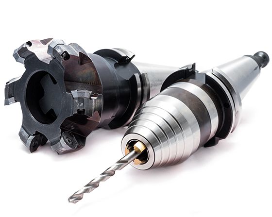
CNC Machining
Precision milling and turning for metal and plastic parts. Prototypes and production.

Sheet Metal Fabrication
Waterjet cutting, laser cutting, tapping, bending and finishes.
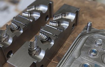
Injection Molding
Injection molding of moderate to larger quantities of plastic parts.
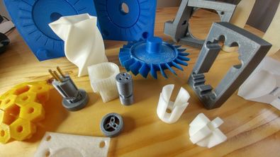
3D Printing
Rapid production of plastic and metal parts. Choose from a variety of colors.

Surface Finishing
Powder coating, anodizing, electroplating, brushing, polishing.

Secondary Processes
A wide variety of secondary machining such as tapping, bending, countersinking.